36c84 Gas Valve Wiring Diagram
Disconnect the pilot generator and operating thermostat wiring from the valve. This includes a WIRING DIAGRAM.
White Rodgers 36c Wiring For 36c84 912 921 36c94 906 Gas Valves Wiring For 36c87 944 Gas Valve
Robertshaw 9615 User Manual Pdf Manualslib.

36c84 gas valve wiring diagram. 7000 derhc series wire diagram manual robertshaw ignition control wiring diagrams 9600 user two stage gas valves thermostat 9520 rinnai r85 valve maple chase products 5600 411 installation data 9615 pdf page 9710 owner s manualzz robert shaw 5 710 502 millivolt dual home heater appliance parts heat pump 400 402 a upgrading to. I show you how to Light the Pil. Https Www Maxoncorp Com Clientuploads Pdf English E Gas Electro Mechanical 32m 05001 01 Pdf.
System wiring wiring for 36c84-926 -936 36c94-907 gas valves 24 vac thermostat limit line 5022 safety timer pilotredundant solenoid valve main valve relay c 36c84 gas valve s 3098 mercury flame sensor hot cold 3 2 4 pressure switch wiring harness. After all gas and electrical connections are com pleted turn gas on and check for gas leaks at both inlet and outlet with leak detection solution or soap suds. Direction Kit Tap Taps.
NAT GAS LP GAS. 3 4 x 3 4 Fast Open 35 2550 Yes Yes. Black pressure switch tant an redundant coil white main relay coil tan tan s l common 42 3 4 terminal panel 1 2 3 4 pilot adj.
36C84-912 Wiring diagrams see pages 250-253 NOTE. Our furnace has quit. This is assuming that the transformer is good and the high limit is closed.
-9XX series replaces -4XX series. Bubbles forming indicate a leak. 3 4 x 3 4 Fast Open.
Use the table on page 1 to identify the proper terminal identification figure for the gas valve. TR The 24v commonreturn side of the transformer. It has a 36C84-201 valve with two wire connection.
This is How to Wire the Thermopile to The 750mv Gas Valve for the Pilot and Main Gas Burners. MANTEL CLEARANCE TOP VIEW OF FIREPLACE BOTTOM LOUVER GAS CONTROL VALVE. Use the table on page 1 to identify the proper terminal identification figure for the gas valve.
If any of the original wire supplied must be replaced use type 18 AWG deg. NAT GAS LP GAS AGA STD. Main valve relay 1 2 redundant pilotvalve 3 4 fig.
Knob replaced with an ON-OFF switch. Wiring diagrams see pages 171-174 Indicates Canadian Model Number SNAP OPEN SINGLE FUNCTION STANDING PILOT GAS VALVES 36C74-913 Step 24VAC Natural 3 4 x 3 4 Step 0935 25-50 No No No Str. It has a 36C84-201 valve with two wire.
With a Redundant Pilot Solenoid Main Gas Regulator Integral Gas Pressure Switch and Electrical Connection on the Gas Valve for Mercury Flame. Our local gas man only has a 36C84-426 vale with 5 wire harness. 5 bi-metal two stage d-1 d-2 w-1 c-1 c-2 pilot w-2 adj.
Thru Yes Yes No 5 Open 136C94-303 24VAC 2 x 3 4 Delay 35 25-50 Yes Yes No Str. System wiring wiring for 36c84-926 -936 36c94-907 gas valves. Our furnace has quit.
It reveals the parts of the circuit as simplified forms and the power and also signal links between the devices. Redundant pilot valve main valve d-2 w-1 w-2 c-2 c-1 hi-lo operator d-1. Emerson White-Rodgers Gas Valve 36C84-926 Natural Gas Fast Open 34 x 34 for Cycle Pilot Systems.
S l com. Disconnect the fryer from the gas and electrical power supplies. CAUTION NOTE Line voltage operating control Line Gas valve High limit Figure 6.
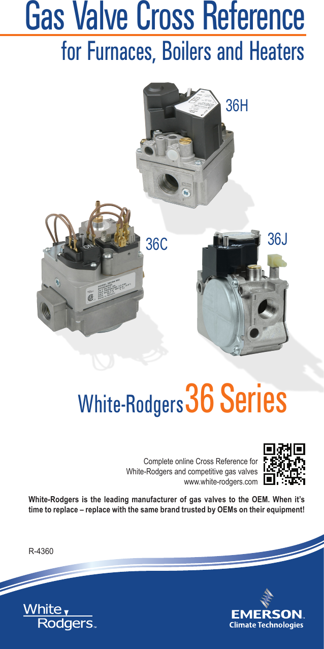
GAS BURNER CONTROLS TECHNICAL HELP Wiring Diagrams. Refer to the wiring diagram on page xx for connecting the wires to the blower. Variety of white rodgers gas valve wiring diagram.
Adjust pilot gas flow for proper flame setting see ADJUSTMENT. Wiring for 36C03A36C13A 120 Volt. With the voltage and frequency shown on the gas control.
Flow Bushing Pressure Side. See pages 250-253 AGA STD. Length maximum or equivalent.
Always refer to wiring instructions provided by Equipment Manufacturer for system hookup operation. THTR This is not internally wired to the gas valve. With a Redundant Pilot Solenoid Main Gas Regulator Integral Gas Pressure Switch and Electrical Connection on the Gas Valve for Mercury Flame Sensor Connection.
Thru Yes Yes No. Thru No Yes No 15. Gas valves 36c wiring information cycle pilot plug-in pilot adj.
GAS VALVES PARTS AND ACCESSORIES See end of this section for parts and accessories 36C84-412 Wiring diagrams see pages 203-206 GAS BURNER CONTROLS TECHNICAL HELP Wiring Diagrams. Set it to the ampere value on the valve label. Not using this makes no difference to the circuit.
Emerson White-Rodgers Gas Valve 36C84-926 Natural Gas Fast Open 34 x 34 for Cycle Pilot Systems. A wiring diagram is a simplified traditional pictorial representation of an electric circuit. See pages 203-206 25K APPLIANCE VALVE Typical Applications Include Gas Heaters FEATURES.
TH The 24v hot leg from the thermostat on a call for heat RW closing to the gas valve TH terminal to open the solenoid to allow gas to flow. The typical wiring diagram shows only the terminal identification and wiring hook up. White Rodgers 36C84-923 - 34 X 34 Gas Valve 24 VAC With Cable Connector For Damper Control Fast Opening - With Redundant Pilot Solenoid Main Gas Regulator Integral Gas Pressure Switch and Electrical Connection on the Gas Valve for Mercury Flame Sensor Connection Features 34 X 34 Gas Valve 24 VAC With Cable Connector For Damper Control Fast Opening.

White Rodgers 36c User Manual Manualzz

36c84 912 White Rodgers 36c84 912 3 4 X 3 4 Gas Valve 24 Vac Redundant Pilot Valve Fast Opening
White Rodgers 36c Wiring For 36c84 912 921 36c94 906 Gas Valves Wiring For 36c87 944 Gas Valve
White Rodgers 36c Wiring For 36c84 912 921 36c94 906 Gas Valves Wiring For 36c87 944 Gas Valve

White Rodgers Furnace Gas Valve Nat Lp 36c84 240 36c84240 36c84 252 36c84252 North America Hvac
36c And 36d Gas Control Product Information

White Rodgers 36c Wiring For 36c84 912 921 36c94 906 Gas Valves Wiring For 36c87 944 Gas Valve
White Rodgers 36c Wiring For 36c84 923 Gas Valve

White Rodgers 36c Wiring For 36c84 913 Gas Valve Wiring For 36c84 916 Gas Valve

How To Wire Light The Pilot Power The Combination Gas Valve Youtube

Wiring Diagram For Furnace Gas Valve Inspirationa Ecobee Wiring Diagram Volovetsfo Wiring Diagram Diagram Thermostat Installation
Emerson 36h Users Manual

White Rodgers Mercury Flame Sensor 3098 3098 3049 User Manual Manualzz

36c84 912 White Rodgers 36c84 912 3 4 X 3 4 Gas Valve 24 Vac Redundant Pilot Valve Fast Opening
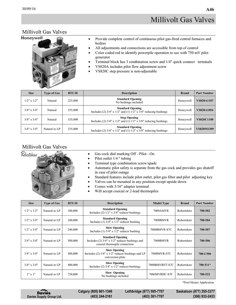
Millivolt Gas Valves Davies Supply Group Ltd Manualzz

Very Strange Buzzing At Gas Valve Heating Help The Wall

36c 36d Installation Instructions Operator Save These Instructions For Future Use Manualzz

Weil Mclane Boiler Inition Issue Heating Help The Wall
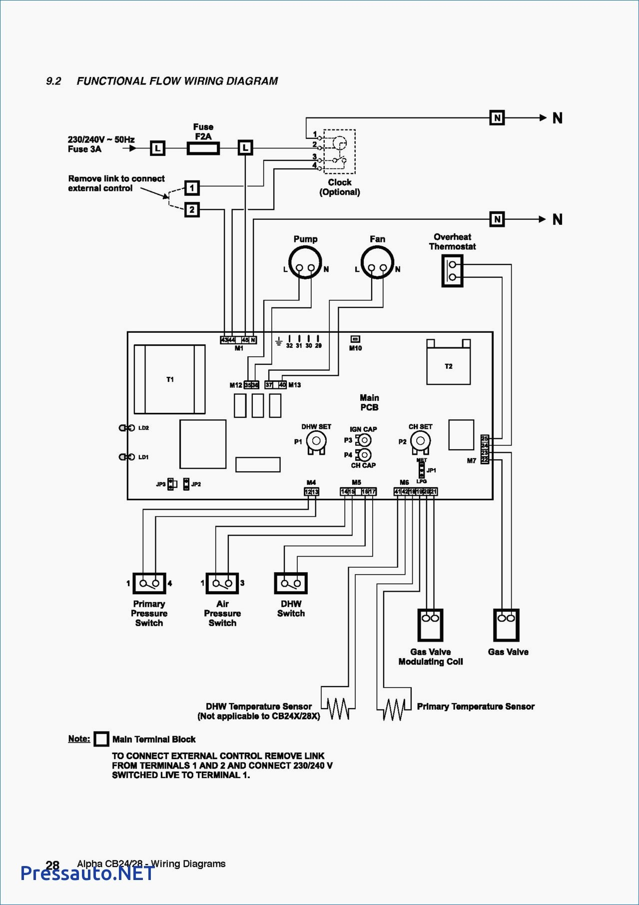
Diagram Diagram Valves Gas Wiring Ef33cw233 Full Version Hd Quality Wiring Ef33cw233 Jobdiagram Amicideidisabilionlus It