1756 Of4 Wiring Diagram
This module is used to drive modulating actuators and devices. 3 View Dimension Drawings 3D Format Catalog Number.
Rslogix 5000 Analog Input Programming Wiring Scaling Tutorial For Plc Analog Input Signal Example
They must be ordered separately.

1756 of4 wiring diagram. Summary of Changes We added information about how to configure the 1756-OB16IEF Redundant Owner. 7 rows 1756-OF4 WIRING DIAGRAM Datasheets Context Search. This module has an output Voltage and Current signals with ranges of - 10VDC and 4-20 mA signals respectively.
It is mechanically keyed to the removable terminal block with mounting torque of 136 Newtons per meter 12 pounds on an inches and it has 22 to 14 AWG strandedsolid copper wire as field side wire. Input and output modules including specifications and wiring diagrams. Ships Today In Stock 1756-OF4 Call For Best Price 1-800-360-6802 Weight.
Wiring System IFM Module Catalog Number Screw RTB required Pushin RTB required Cable Cat. Additional grounding connections from the power supplys mounting tabs or DIN rail if used are not required unless the mounting surface cannot be grounded. 4-13 Wiring the 1756-IF16 Module.
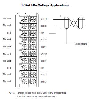
Windows Meta-File WMF 1756-OF4. Wiring Diagram 1756-OF4 Voltage 4 Channel Input Output or 2 Input 2 Output 3 F 1492-AIFM4-3 1492-ACABLEVA 41170-493. See 1756 Removable Terminal Blocks on page271 and Wiring Systems on page272.
Allen bradley 1756 of8 wiring diagram sample wiring assortment of allen bradley 1756 of8 wiring diagram a wiring diagram is a simplified standard pictorial representation of an electric circuit it shows the parts of the circuit as streamlined shapes and also the power and also signal connections between the gadgets a wiring diagram generally provides details regarding the loved one position and arrangement of tools and also terminals on the 1756 of8 wiring diagram 1756 of8 wiring diagram. Automation Wiring and Grounding Guidelines publication 1770-41. Product Compatibility and Download Center.
The 1756-OF4 is a ControlLogix Four 4 channel analog output module. For mounting instructions see Mount Module to Panel by Using the Dimensional Template or Mount Module to a DIN Rail. You must be able to program and operate a ControlLogix controller to use your digital IO module efficiently.
Simplified Block Diagram Install the 1769-OF4 Module Attach the module to the controller or an adjacent IO module before or after mounting. PLC Card Wiring System 7SH M Description Terminals Per Channel Fixed or Removable 7HUPLQDOV Wiring System IFM Module Catalog Number Screw RTB required Push-in RTB required Cable Cat. 6x6x3In Repair Your 1756-OF4 Call For Assitance 1-800-360-6802.
1756-OF8 1756-IF16 1756-IF8 1492-AIFM8-3 WIRING 1756-OF4 1756-IR6I 1492-AIFM8-3 1756-OF4 WIRING DIAGRAM 1756-IF6I Text. 142 Wire the 1756-OF4 Module. 144 1756-OF4 and 1756-OF8 Module Fault and.
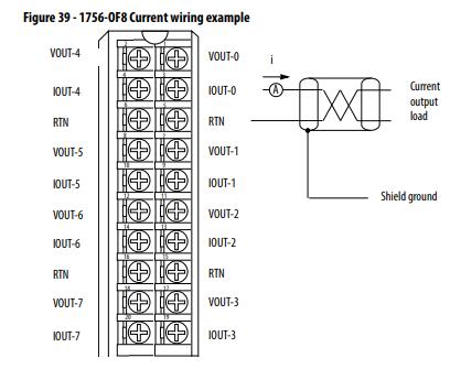
143 Wire the 1756-OF8 Module. Standard IO Module Wiring 1756 ControlLogix standard IO modules require either a Removable Terminal Block RTB or a 1492 interface module IFM to connect all field-side wiring. The 1756-OF4 has a 250 Volt AC voltage isolation between output channel to the backplane using reinforced insulation type tested at 1350 Volt AC for 2 seconds and it is electronically keyed to the controllogix chassis via digital control.
Updated diagram labels for wiring the 1756 if6i module chapter 6 updated fahrenheit temperature conversion range values for cold junction compensation types and cold junction offset option added advisory not to exceed the spec ific isolation voltage when using a separate power source when wiring various modules. Download our 1756-OF4 Wiring Diagram. AutoCAD DWG Drawing Interchange Format DXF Adobe PDF.
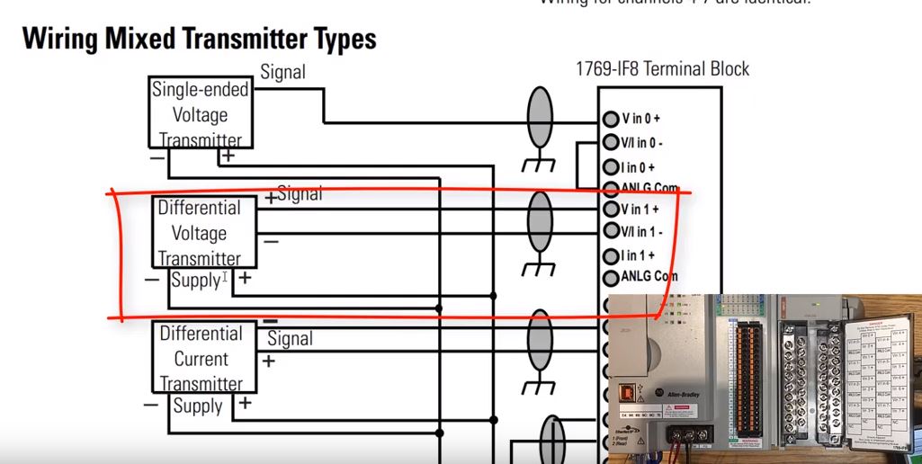
Mounting Dimensions ATTENTION This product is intended to be mounted to a well-grounded mounting surface such as a metal panel. Field Side Circuit Diagrams. Analog currentvoltage input module 36 pin Chapter 4 1756- IF8 8 -point non-isolated analog ControlLogix Analog IO Modules 1756-IF16- IF6CIS.
RTBs and IFMs are not included with the IO modules. Ships Today In Stock 1756-OF4 Call For Best Price 1-800-360-6802 Weight. 3 Racks 12 DI modules per type 10 DO modules per type 10 AI modules per type 6 AO modules per type.
6x6x3In Repair Your 1756-OF4 Call For Assitance 1-800. Catalog Datasheet MFG Type. Configure the PLC racks with available modules in the drop-down boxes.
Before making the wiring diagrams you can use the arquitecture builder from Rockwell Automation. Troubleshooting and Product Information for 1756-OF4 Download product information troubleshooting guides and operation manuals to get your PLC operational. Download our 1756-OF4 Wiring Diagram.
Wiring Diagram 1756OF4 Voltage 4 Channel Input Output or 2 Input 2 Output 3 F 1492AIFM43 1492ACABLEVA 41170 493 3 R 1492RAIFM43 RTB8N RTB8P 1492ACABLEVA 41170. To work with a system that. How to use it.
Open wire Off-state leakage current 15 mA min Loss of power Transition range 4685V AC Timestamp of diagnostics 1 ms Table 2 - Technical Specifications - 1756-IA8D Attribute 1756-IA8D Inputs 8 diagnostic 4 pointsgroup Voltage category 120V AC 5060 Hz Operating voltage range1 79132V AC 4763 Hz Input voltage nom 120V AC 5060 Hz.
Https Literature Rockwellautomation Com Idc Groups Literature Documents In 1492 In132 En E Pdf

Wire The 1756 Of4 Module Rockwell Automation 1756 Xxxx Controllogix Analog I O Modules User Manual Page 157 401

Diagram Cc3d Flight Controller Wiring Diagram Free Picture Full Version Hd Quality Free Picture Veediagram Amicideidisabilionlus It
Diagram 1991 1999 Mitsubishi Pajero Service Workshop Manual Wiring Diagram Manual Full Version Hd Quality Diagram Manual Imdiagram Segretariatosocialelatina It

Welcome Thank You For Joining Us We Ll Get Started In A Few Minutes Ppt Download
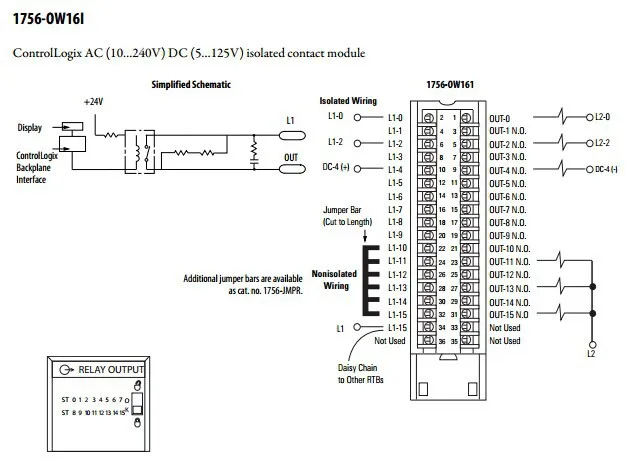
Allen Bradley Plc Pemrograman 1756 Ow16i 16 N O Output Terisolasi Terpisah Dengan Harga Terbaik Buy Ac Dc Terisolasi Hubungi Modul Analog Output Modul Plc Pengukur Amper Dengan Output Product On Alibaba Com
Diagram G35 Coupe Parts Diagram Electrical Full Version Hd Quality Diagram Electrical Veediagram Amicideidisabilionlus It


How To Wire A Proximity Sensor To A Plc

How To Wire A Proximity Sensor To A Plc

Motor Wiring Dual Wiring Diagram Xdvd110bt Of 4 Ohm Voice Coil Subwoofer Inr Wiring Diagram 89 Wiring Diagrams Rokok Elektronik Vape Teknik Listrik

Tvs Motorcycle Engine Diagram Trailer Wiring Diagram Wiring Diagram Motorcycle Wiring

Diagram Guitar Input Wiring Diagram Full Version Hd Quality Wiring Diagram Imdiagram Amicideidisabilionlus It

Speakon Connectors Wiring Drawing 01 Vision Entertaining Connector Of 4 Pole Speakon Wiring Diagram On 4 Pole Speakon Wiring Diagra Math Math Equation My Saves

Welcome Thank You For Joining Us We Ll Get Started In A Few Minutes Ppt Download
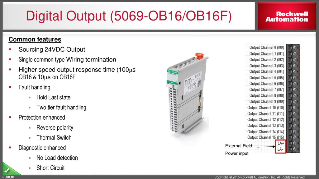
Allen Bradley Plc 1756 Ob32 Controllogix Modules Ab 1756 Ob32 A New For Sale Allen Bradley Modules Manufacturer From China 108564786


Pin On Speakon
1756 If4xof2f Ma Current Mode Wiring Youtube
Allen Bradley 1756 Of8 1756 Of4 1756 Of4k 1756 Of8i 1756 Output Module Oleh Pt Total Abadi Solusindo Authorized Distributor General Contractor Di Jakarta Timur
Allen Bradley 1756 Of8 1756 Of4 1756 Of4k 1756 Of8i 1756 Output Module Oleh Pt Total Abadi Solusindo Authorized Distributor General Contractor Di Jakarta Timur